What is insulation?
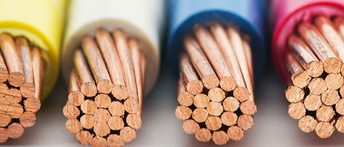
Electrical conductors within cables, switchgear and machines are usually manufactured from copper or aluminium. Whilst both copper and aluminium boast fantastic conductive properties which make them ideal conductors, the insulating material surrounding them must the opposite in order to resist the current flow, keeping the flow of electrons on the correct path. These materials are known as insulators.
What causes insulation to fail?
As nearly 80% of electrical testing involves us testing insulation for integrity, it is important to understand the factors which contribute towards the degradation of insulation:
- Temperature – both hot and cold extremities of temperature will cause insulation to expand and contract causing cracks over time.
- Electrical – Specific cable types are manufactured for certain installation methods. Using an incorrect cable product may expose insulation to both over-voltage and under-voltage conditions leading to degradation.
- Physical – damage caused by blunt trauma will almost certainly have an effect on an insulator, as can vibration caused by running machinery out of phase or infrequently.
- Chemical – motor bearing oil, general plant grime and dust can have adverse chemical effects on cable insulation.
- Environment – environmental conditions will almost always have an effect on cable insulation. PVC will react to UV rays over time, whilst fauna and flora can influence insulation resistance values.
As a result of the above, both the reliability and the safety of an electrical installation can become an unwanted issue should insulation resistance values are not tested regularly and monitored.
How is insulation resistance calculated and tested?
We should all be familiar with Ohm’s law. If we apply a voltage across a resistor and then measured the consequential current flow, we can then use the formula R=U/I, (where U=Voltage, I=Current and R=Resistance) to calculate the resistance of the insulation. This is a very basic method indeed and we must be aware of the many different types of current which are consequence to the insulation resistance test. These include capacitive charge current , polarization current, leakage current and conduction current.
Insulation resistance is calculated using an insulation resistance tester. Generally, two leads are connected into a circuit in order to carry out the test. How and where these two leads are connected will differ depending on what the test subject may be. A third lead, which may or may not be available for your tester, will connect to a guard terminal. The guard terminal acts to allow you to be selective in evaluating specific electrical components in a large piece of plant machinery, for example.
What voltages should I test at and what results will I expect to see?
The answers to both of these questions will depend on what your test application, and which regulations you are using. The tables below are extracted from BS7671:2008 Amendment 1 (Requirements for Electrical Installations) and IEEE Std 43-2000 (IEEE Recommended Practice for Testing Insulation Resistance of Rotating Machinery:
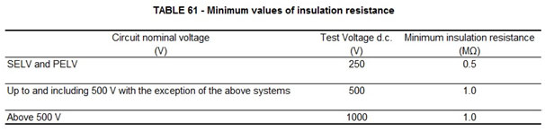
Above: BS7671:2008 Amendment 1 (Requirements for Electrical Installations)
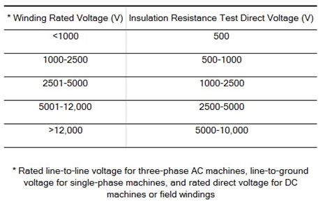
Above: IEEE Std 43-2000 (IEEE Recommended Practice for Testing Insulation Resistance of Rotating Machinery)
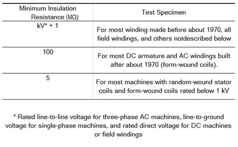
Above: IEEE Std 43-2000 (IEEE Recommended Practice for Testing Insulation Resistance of Rotating Machinery)