- GFL-1500 Transmitter
- GFL-1500 Receiver
- GFL-1500 Clamp
- MC4 Test Leads 1500 V rated test leads
- Alligator clips
- MC4 unlocking tool
- Soft carrying case
- Backpack style shoulder strap
- 14x AA Alkaline batteries
Fluke GFL-1500 Solar PV Ground Fault Locator

SKU: FLUKEGFL1500
- Identifies and locates active ground faults in solar PV systems rated up to 1500V
- Reduces troubleshooting time with easy-to-follow traceable signal
- CAT III 1500 V DC/CAT IV 600 V rated transmitter and receiver
Use reward points to get money off future purchases.
Please note: Customers must be signed into their account to be elegible. Find out more about reward points here.
Found this product cheaper & in stock somewhere else? Give us the details and we'll endeavour to match the price.
To price match, contact us online or call 0113 248 9966.
We offer FREE standard delivery on all orders over £249, with a range of next-day options also available on many items.
Find out more on our delivery information page.
We want our customers to be fully satisfied with the goods they purchase from us, offering returns for up to 60 days.
Find out more about our refunds policy here.
We're always happy to offer help, information & advice to find the right instrument for you, so please get in touch.
To speak to our sales team, call us on 0113 248 9966, use our Live Chat service or contact us online.
Fluke GFL-1500 Solar PV Ground Fault Locator
The Fluke GFL-1500 Ground Fault Locator is a frontline troubleshooting tool designed to help technicians quickly identify hard ground faults in solar photovoltaic (PV) systems rated up to 1500V. Unlike traditional fault-finding methods that can be time-consuming, complicated and often rely on guesswork, the GFL-1500 streamlines this process by injecting a traceable signal directly into the PV circuit, allowing technicians to find faults faster and more accurately. Once the signal is introduced into the circuit, technicians use the signal tracing clamp or receiver to follow the path of the signal right up to the fault location. This reduces downtime, improves efficiency, and enhances the accuracy of maintenance and repair work on solar installations.
System components
The GFL-1500 features a three-piece system that consists of
- GFL-1500 Transmitter – injects the traceable signal into the PV array.
- GFL-1500 Receiver – detects the signal along the array, guiding technicians to the fault location.
- GFL-1500 Signal Tracing Clamp – enables non-contact detection, improving workflow safety and efficiency.
Together they improve workflow safety and efficiency, providing an end-to-end solution that not only confirms the presence of a fault but also guides users directly to its exact location. Designed for modern solar environments, the GFL-1500 meets stringent international safety standards and is rated CAT III 1500 V and CAT IV 600 V, making it safe to use in high-voltage environments and gives site managers greater assurance in system performance and uptime.
FaultTrack™ Technology
At the heart of the GFL-1500 lies Fluke’s FaultTrack™ Technology, which generates a traceable signal through the active fault path. Technicians can follow this signal from the transmitter, through the PV circuit, to the exact point of failure. In large or complex solar arrays, this technology eliminates the guesswork and reduces reliance on site diagrams, helping technicians identify faulted strings and branches with remarkable precision. The combination of non-contact tracing and advanced diagnostics makes the GFL-1500 one of the most effective and user-friendly fault locators on the market.
Basic Diagnostic Functions
The GFL-1500 has several dignostics functions made to streamline fault detection in solar PV systems. The first is Analyse function, which measures the open-circuit voltage between the positive and negative terminals, as well as from each terminal to ground. If a fault exists, the system estimates the fault resistance and can even approximate the fault location when the number of modules per string is entered. The next is Fault function. Once activated, the GFL-1500 injects a traceable signal that technicians can follow using the clamp or receiver. This function allows for quick and precise fault pinpointing without needing to isolate strings or disconnect conductors unnecessarily.
For cases where a conductor break (rather than a ground fault) is causing the issue, Open Circuit function helps trace where the open circuit occurs. It is particularly useful for diagnosing inactive strings that produce no current or fail to trigger ground-fault detectors. And lastly, Mapping function is ideal for sites with poor or outdated system documentation. It enables users to trace healthy strings, confirm wiring layouts, and verify system connections, all without relying on incomplete or inaccurate site maps.
Applications Across the Solar Industry
The Fluke GFL-1500 is purpose-built for:
- Solar O&M (Operations and Maintenance) teams
- Commissioning engineers
- System integrators
- Utility-scale and rooftop PV system technicians
It is especially effective for detecting faults that cause inverter shutdowns, leakage current alarms, or performance drops. During commissioning, it helps confirm wiring integrity and detect accidental ground paths before system energisation. By simplifying fault-finding, the GFL-1500 improves system uptime, increases energy yield, and boosts site reliability.
More on the system components
| GFL-1500 Transmitter | GFL-1500 Receiver | GFL-1500 Clamp | |
|---|---|---|---|
| Measurement Category | CAT III 1500 V DC / CAT IV 600 V | CAT III 1500 V DC / CAT IV 600 V | Not category rated. Use on insulated conductors only, up to 1500 V |
| Operating Voltage | 1500 V DC / 600 V AC | 1500 V DC / 600 V AC | Non-contact. Use on insulated conductors only, up to 1500 V |
| Trace Signal Operating Frequency | FAULT & MAP: 6.25 kHz OPEN: 32.764 kHz |
FAULT & MAP: 6.25 kHz OPEN: 32.764 kHz |
|
| Trace Signal Indications | Graphical display, audible beep | Numeric, bar graph display, audible beep, LED | AC current |
| Trace Signal Current Output (typical) | FAULT & MAP (Array HIGH): 30 mA RMS FAULT & MAP (Array LOW): 6 mA RMS Unit HIGH: 120 mA RMS OPEN HIGH: 100 mA RMS OPEN LOW: 30 mA RMS |
||
| Trace Signal Voltage Output (typical) |
FAULT & MAP: Unit HIGH: 30 V RMS |
||
| Voltage range/Rosolution (Analyse) | Range: 0-1500 VDC Resolution: 1V No voltage measurement if high capacitance & resistance detected |
||
| Range Detection (typical) | FAULT & MAP Array Mode: up to 4.75 m (15.6 ft) FAULT & MAP Unit Mode: up to 5.9 m (19.4 ft) OPEN Mode: up to 2.7 m (8.9 ft) |
||
| Resistance Ranges (Analyse) |
≈ <5 kΩ (FAULT) No resistance reange if high capacitance & resitance detected |
Range: 0–1500 V DC Resolution: 1 V No measurement if high capacitance & resistance detected |
|
| AC Current Measurement | Range: 150 mA Resolution: 0.1 mA Max Conductor Diameter: 61 mm |
||
| Display | Graphic LCD Display with front light | Segment LCD Display with back light | Segment LCD Display with back light |
| Operating temperature | -20 °C to 50 °C | -20 °C to 50 °C | -10 °C to 50 °C |
| Operating humidity (non-condensing) | 95 %RH: 0 °C to <30 °C 75 %RH: 30 °C to <40 °C 45 %RH: 40 °C to 50 °C |
||
| Operating altitude | 0 to 3,000 m | ||
| Storage altitude | 0 to 12,000 m | ||
| Storage temperature and humidity (without batteries) | -20 °C to 70 °C, <95 %RH | -20 °C to 70 °C, <95 %RH | -40 °C to 60 °C, <95 %RH |
| Transient protection | 0.00 kV (1.2/50 μs surge) | ||
| Pollution degree | 2 | ||
| IP rating | IP54 | IP54 | IP30 (Jaw Closed) |
| Drop test | 1 m | ||
part number: FLUKE-GFL-1500
Key features
- Identify and locate active ground faults in PV systems
- Reduce troubleshooting time with easy-to-follow traceable signal
- Decrease exposure to hazards with non-contact tracing
- Analyse, Fault Tracing, Open Circuit, and Mapping functions
- CAT III 1500 V DC/CAT IV 600 V rated transmitter and receiver
Specialists In Solar PV Test Equipment
Watch the video above to see how we can help you find the right solar pv test equipment & get in touch on 0113 248 9966 or sales@test-meter.co.uk.

As a leading Solar PV Test Equipment and Solutions provider in the UK, we have a wide range of expertise. Whether you're conducting simple commission tests, small-scale 1000V solar PV rooftop installations or 1500V commercial solar farms to more in-depth IV curve trace analysis, our team ensures your enquiry is looked after from start to finish, providing you with the perfect solution.
Find the best solution for your application and budget through:
- Onsite-demo/remote consultations on request
- 'Try Before You Buy' and hire options available
- After-sales care that provides ongoing calibration and servicing
- Finding the optimal software package, ensuring the correct reporting and data functionality for your needs
Can't find the right Solar PV Test Equipment or solution? We're on hand to help, please get in touch on 0113 248 9966 or sales@test-meter.co.uk
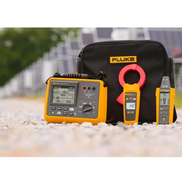
What's In The Box?
Transmitter SpecificationsMeasurement Category: CAT III 1500 V DC / CAT IV 600 V Operating Voltage: 1500 V DC / 600 V AC Trace Signal Operating Frequency: Trace Signal Indications: Graphical display with audible beep Trace Signal Current Output (Typical): Trace Signal Voltage Output (Open Circuit, Typical): Voltage Range / Resolution (ANALYZE): Resistance Ranges (ANALYZE): Transient Protection: 10.00 kV (1.2/50 μS surge) Display Type: Graphic LCD display with front light Operating temperature: –20 °C to 50 °C (–4 °F to 122 °F) Operating humidity (non-condensing): Operating altitude: 0 to 3000 m (9843 ft) Storage altitude: 0 to 12 000 m (39 371 ft) Storage temperature and humidity (without batteries): –20 °C to 70 °C (–4 °F to 158 °F), <95 %RH Pollution degree: 2 IP rating: IP54 (non-operating) Drop test: 1 m (3.28 ft) Power supply: 8 × AA IEC LR6 alkaline or NiMH rechargeable batteries Battery life (typical): Low battery indication: Yes Dimensions (L × W × H): 244 × 180 × 106 mm (9.6 × 7.0 × 4.2 in) Weight (with batteries): 2.04 kg (4.5 lb) Receiver SpecificationsMeasurement Category: CAT III 1500 V DC / CAT IV 600 V Operating Voltage: Non-contact, safe for use on insulated conductors up to 1500 V Trace Signal Indications: Numeric and bar graph display with audible beep and LED indicators Range Detection (Typical): Display Type: Segment LCD display with backlight Operating temperature: –10 °C to 50 °C (14 °F to 122 °F) Operating humidity (non-condensing): Storage altitude: 0 to 12 000 m (39 371 ft) Storage temperature and humidity (without batteries): –40 °C to 60 °C (–40 °F to 140 °F), <95 %RH Pollution degree: 2 IP rating: IP54 Drop test: 1 m (3.28 ft) Power supply: 4 × AA IEC LR6 alkaline or NiMH rechargeable batteries Battery life (typical): ~16 h Low battery indication: Yes Dimensions (L × W × H): 183 × 75 × 43 mm (7.2 × 2.95 × 1.69 in) Weight (with batteries): 0.27 kg (0.6 lb) Clamp SpecificationsCategory Rating: Not category rated. Use on insulated conductors only (up to 1500 V). Operating Voltage: Non-contact; use on insulated conductors only, up to 1500 V. Trace Signal Indication: AC current detection AC Current Measurement: Display: No display (data viewed via receiver) Operating temperature: –10 °C to 50 °C (14 °F to 122 °F) Operating humidity (non-condensing): Pollution degree: 2 IP rating: IP30 (jaw closed) Drop test: 1 m (3.28 ft) Power supply: 2 × AA IEC LR6 alkaline batteries Battery life (typical): >150 h (without backlight and spotlight) Dimensions (L × W × H): 257 × 116 × 46 mm (10.1 × 4.6 × 1.8 in) Weight (with batteries): 0.6 kg (1.32 lb) |